Categories
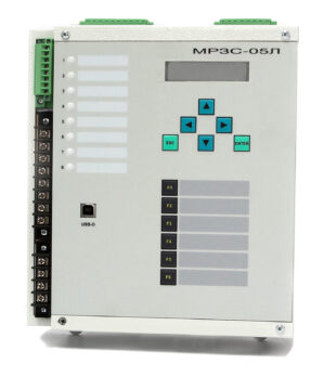
MРЗС-05Л АИАР.466452.001-32.04
It is used as an ATS device in 0.4 - 150 kV networks. Optimized to perform the ATS function in 0.4 kV networks.
Performs the following functions:
Provides control and measurement of the following quantities:
- three currents: one phase input 1, one phase input 2, one phase intersection;
- three phase/line voltage input 1;
- three phase/line voltages input 2;
- mains frequency on both inputs;
- angles between all currents and voltages.
Relay protection functions:
- four-stage undervoltage protection with AND or OR triggering,
- four-stage overvoltage protection with AND or OR triggering.
Automation and control functions:
- automatic switching on of the reserve (ATS) with the ability to work not only for lowering, but also for increasing voltage;
- Automatic Normal Mode Restore (AVHR)
- control of switches of inputs and SV,
- monitoring the switching resource of the circuit breaker,
- phasing control.
Functions, triggers and gates being defined:
- number of defined functions - 8;
- the number of triggers being defined is 4, the state of the triggers is stored in nonvolatile memory;
- logical gates AND, OR, NOT, EXCLUSIVE-OR.
Universal emergency waveform recorder with digital signal recording:
- parameterizable recording duration of pre-alarm, alarm and post-alarm processes.
- the resolution of the recorder by analog signals - no more than 1.25 ms.
- total recording duration - 50 seconds.
Digital signal recorder:
- 80 latest crashes,
- up to 43 records in each alarm with a time interval of 1 ms,
- for each accident are recorded:
- all input and output discrete signals, with fixed arrival and departure times;
- actuation of all protection and automation organs;
- Toggle switches on and off.
Number of freely programmable inputs, outputs, indicators:
- digital inputs - 10;
- discrete relay outputs - 10, without and with memory, implementation of SHMS;
- LED indicators - 8, with and without memory.
Connection diagram МРЗС-05Л АИАР.466452.001-12.04, (-32.04)
Connection diagram МРЗС-05Л АИАР.466452.001-12.04, (-32.04)
Overall and connecting dimensions MRZS-05L AIAR.466452.001-12.04(-32.04)
Overall and connecting dimensions МРЗС-05Л АИАР.466452.001-12.04(-32.04) -1
Overall and connecting dimensions МРЗС-05Л АИАР.466452.001-12.04(-32.04) - 2
Overall and connecting dimensions МРЗС-05Л АИАР.466452.001-12.04(-32.04) - 3
Overall and connecting dimensions МРЗС-05Л АИАР.466452.001-12.04(-32.04) - 4
Overall and connecting dimensions МРЗС-05Л АИАР.466452.001-12.04(-32.04) - 5
Overall and connecting dimensions МРЗС-05Л АИАР.466452.001-12.04(-32.04) - 6
Software WisiNet_2 for МРЗС-05Л, МРЗС-05Д, MRZS
Please pay attention! Many new versions of devices have been added for corrective work, the program must save the /data folder (with your archives), delete the WisiNet2 installation program, download the archive from the website and install the Wisinet2 program and replace the new /data folder with your previous oneDownload Wisinet 2


